Continuing my series of talking about my adventures in building an FPGA game console, today I’ll talk about how I familiarized myself with the SNES gamepad serial protocol and got a working physical hardware prototype of being able to query the button states.
Now, unfortunately, my FPGA board still hasn’t arrived (it’s scheduled to arrive tomorrow according to UPS), so until then I can’t do much actual testing of FPGA-related things – aside from running simulated testbenches I suppose. However, I do have a Propeller Activity Board WX on hand, so I decided to do some prototyping there to make sure I knew how to talk to the gamepad and make sure I could wire things up right.
The first thing I did was purchase an after market SNES gamepad in addition to an extension cable. I snipped open the extension cable and used a multi-meter to test each wire inside and write down how each one mapped to the pins in the front-facing part that the controller would plug into. I did this to an extension cable rather than the controller itself so that I wouldn’t have to cannibalize a controller – yay reusability!
So, as for the pinout, they’re actually really simple. There’s only five wires I care about, and they are mapped as follows:
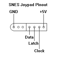
Now, +5V and GND are obvious. That leaves me with three IO lines to worry about: Clock, Latch, and Data. What do these do?
It turns out the inner workings of a SNES controller are actually dead-simple: nothing more than a couple of shift register ICs. The first step to getting the button states is Latch: pulsing Latch high and then low, for a period of at least 12us, causes the shift register chips inside the controller to capture the state of each of its input pins (which are each wired directly to a button!). Once that’s done, the Data will now be high or low depending on the state of the B button (low if the button is pressed, high if the button is released).
Next, to get the rest of the buttons, you just need to start pulsing the Clock line with a period of at least 12us. Each high/low pulse will cause the shift register chips to shift out another button state on the Data line. The button states you get are mapped to these clock cycles as follows:
- First Latch pulse: B button
- Clock 1: Y button
- Clock 2: Select button
- Clock 3: Start button
- Clock 4: D-pad Up
- Clock 5: D-pad Down
- Clock 6: D-pad Left
- Clock 7: D-pad Right
- Clock 8: A button
- Clock 9: X button
- Clock 10: L shoulder button
- Clock 11: R shoulder button
Alright, with that being said, onto getting this wired up to my Propeller board.
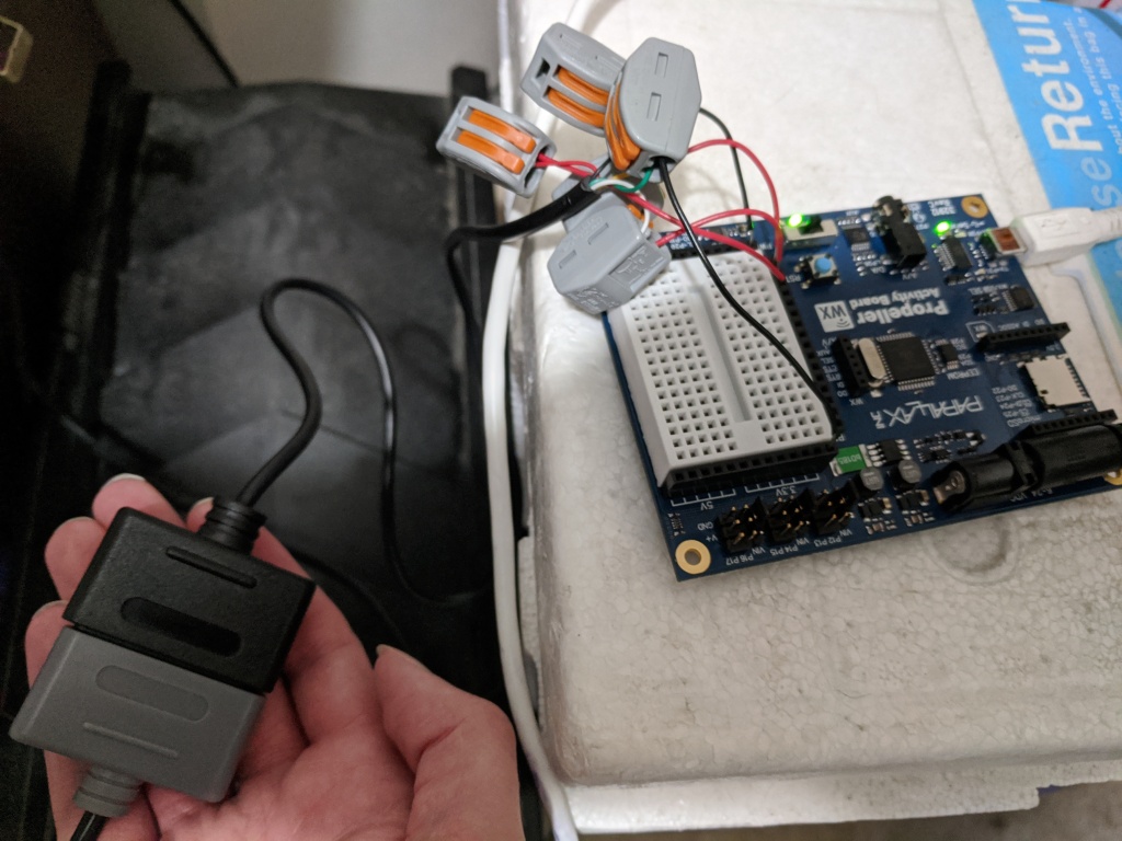
I stripped each wire inside the controller extension cable and used a multimeter to figure out which of these wires were power, ground, latch, clock, and data. Once I did that, I used some WAGO connectors I had lying around to attach solid-core wires to each one to make it easier to connect them to a breadboard. It looks fugly as hell, but it should do the job.
Before I wired up the controller cable to live power, I did some reading to ensure I knew what I was doing. It turns out, while the above diagram (and many, many others I found) says +5V, that’s actually apparently a bad idea, as it might mean you get +5V on the output Data line too – and my board only accepts 3.3V GPIO lines! However, the controller will run just fine off of 3.3V power too, so I went with that.
I plugged the power wire into a 3.3V header on my Propeller board, the ground wire into a Ground header, and clock, latch, and data wires into P0, P1, and P2 headers respectively.
My first test was just to pulse the latch and see if I could get back something on data. I used Prop-C for the task, throwing together some quick code that changed the delay dt to have a length of about 6us for every 1 unit, pulsed the latch line, waited 1 unit, pulled the latch line low, and then set one of the board LEDs to the inverse of the Data line (since it’s active low, so 0 = button pressed).
I plugged everything in, hit Run With Terminal, and….. nothing happened. No LED light. None of my print messages arrived in the terminal. Huh?
I would assume my print messages would show up at least. That led me to an interesting discovery: You can’t set the delay DT value too low or calling pause will just lock up the propeller. I don’t know why this is and it’s undocumented, so I assume it’s a bug in their library. The good news, though, is that the controller isn’t super sensitive to timing – you can pulse the latch and clock lines extremely slowly and it will still work perfectly fine.
So I fixed that little mistake and recompiled. This time I got logs back from the device, but still no LED lights.
At this point I kind of panicked. Oh no, please tell me I did not just wire up something backwards. Images of a fried game controller came to mind. I immediately grabbed the multimeter and started carefully testing each pin on the controller connector. Power looked good. Wrote a little test program to pulse clock on and off once per second. Multimeter picked up a 0 – 3.3V regular pulse. Same program for latch. Multimeter picked that up too.
So my power, ground, clock, and latch lines were all wired correctly. There was only one wire remaining, so there was no way that one could have been wrong either.
Well, it turned out my mistake was in how I was checking the input data line. Removing the bit-reverse operator immediately fixed the problem, only now the LED lit up when the B button wasn’t pressed and turned off when it was! But at least I was getting back controller data.
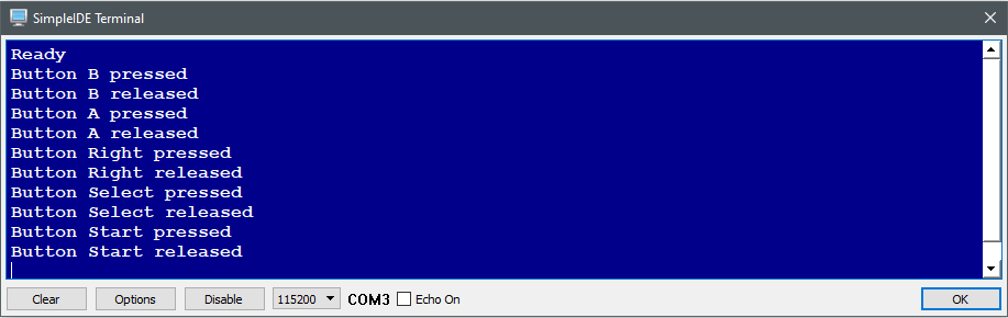
From there it didn’t take very long at all to wire up the full clock cycle loop and get back the entire controller state. I had it keeping track of previous and current controller states as a bitmask and logging whenever these changed so that I could log when buttons were pressed and released, and it all works 100% as intended!
Now obviously I’m not going to be using a Propeller for the final product, but this was just a proof-of-concept to prove to myself that I could wire up and communicate with a SNES controller. Once my FPGA board arrives I intend to do the same thing but in a bespoke FPGA module rather than a microcontroller.
